Intelligent Machines Lab

Everything we built

Back to IML
The cell's vacuum table

Built in-house.

Two ABS plates from our CAD, milled in the shop.

  • Top plate · ABS 19 mm · 23.2 mm squares, 6.8 mm grooves
  • 21 × M6×30 screws · 16 at the edge, 5 inside
  • Bottom plate · ABS 19 mm · seal groove 5 × 6 mm
  • 876.5 × 936.5 mm · 9 vacuum ports Ø33.6
Top plate · 876.5 × 936.5 mmABS, 19 mm. 23.2 mm squares, 6.8 mm grooves 7 mm deep. 9 vacuum ports, Ø33.6
21 × M6×3016 at the edge, 5 in the middle of a square. Threads cut by hand, 16 mm deep
Bottom plateABS, 19 mm. Seal groove 5 × 6 mm, 25 mm in from the edge

Holders, from our CAD

Printed, keyed into the table grid.
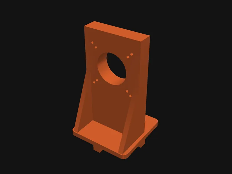
Printed camera holder
Camera holder
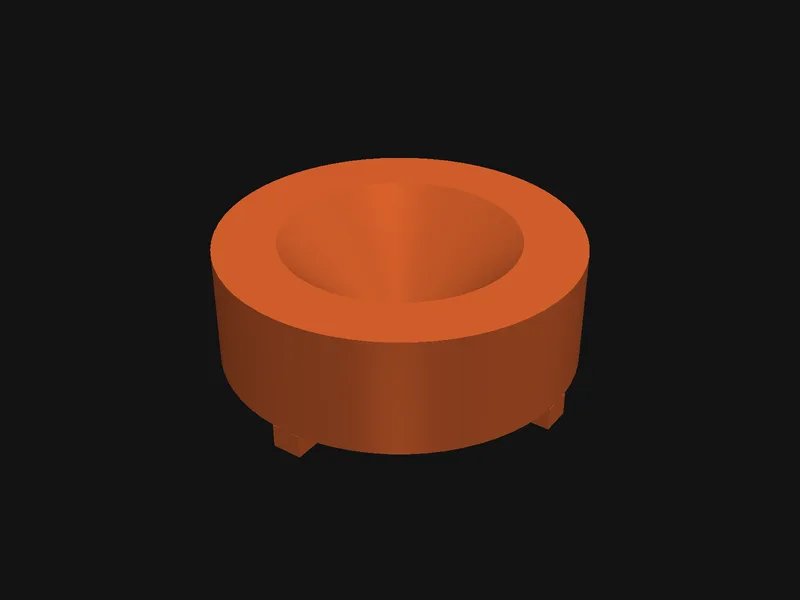
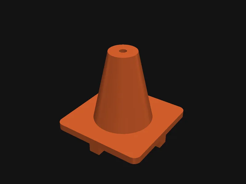
Printed cone ring
Cone ring
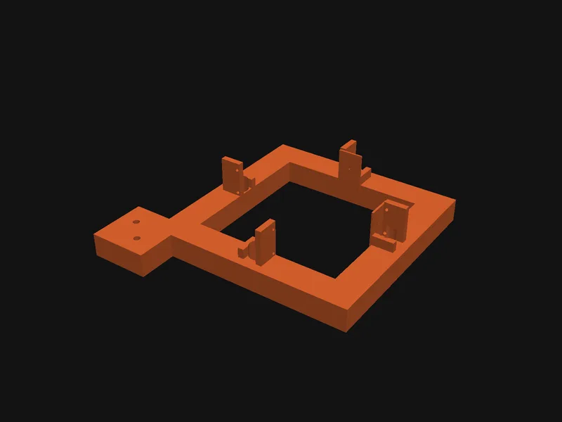
Printed laser cross frame
Laser cross frame
Printed reference pin holder
Reference pin holder
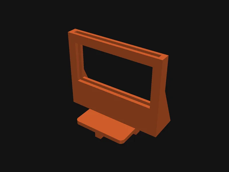
Printed light panel frame
Light panel frame
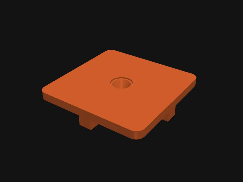
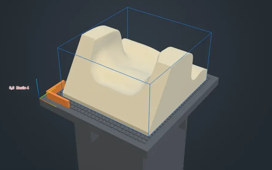
Printed corner locator
Corner locator
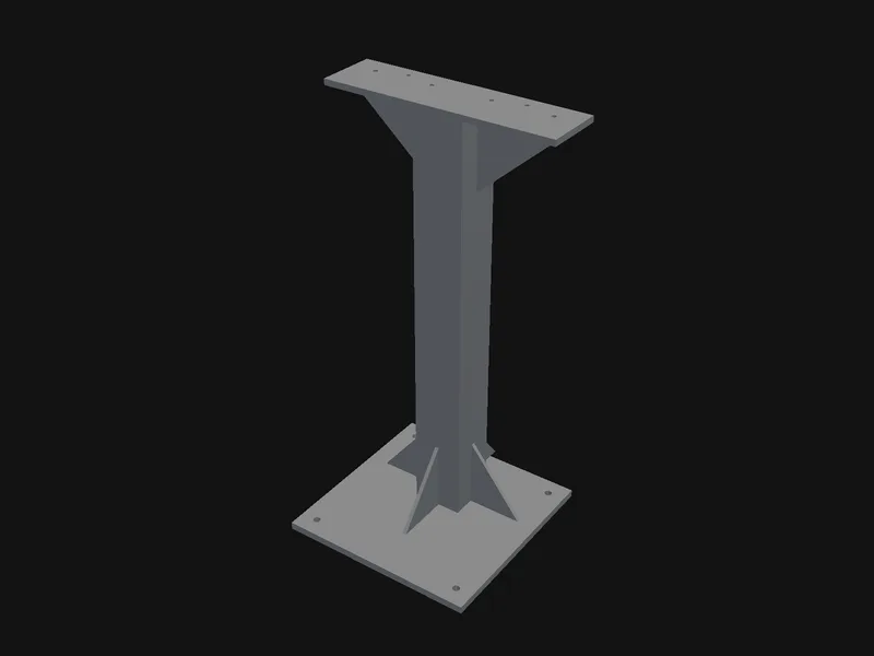
Welded steel stand
Laser stand · welded steel
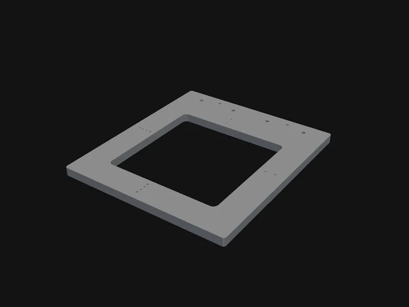
Laser frame plate
Laser frame plate

The robot measures its own tools

Camera in use since 12 Oct. Laser and cone ring: renders.

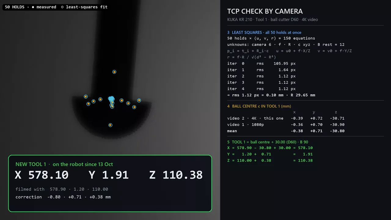
Real run: 50 poses in front of the camera, new tool point on the controller
Laser cross · render
Camera cross · render
Cone ring · render

Our own touch probe

In development. Not built yet, the firmware runs in a digital twin for now.

On a touch the infrared band lights up · render
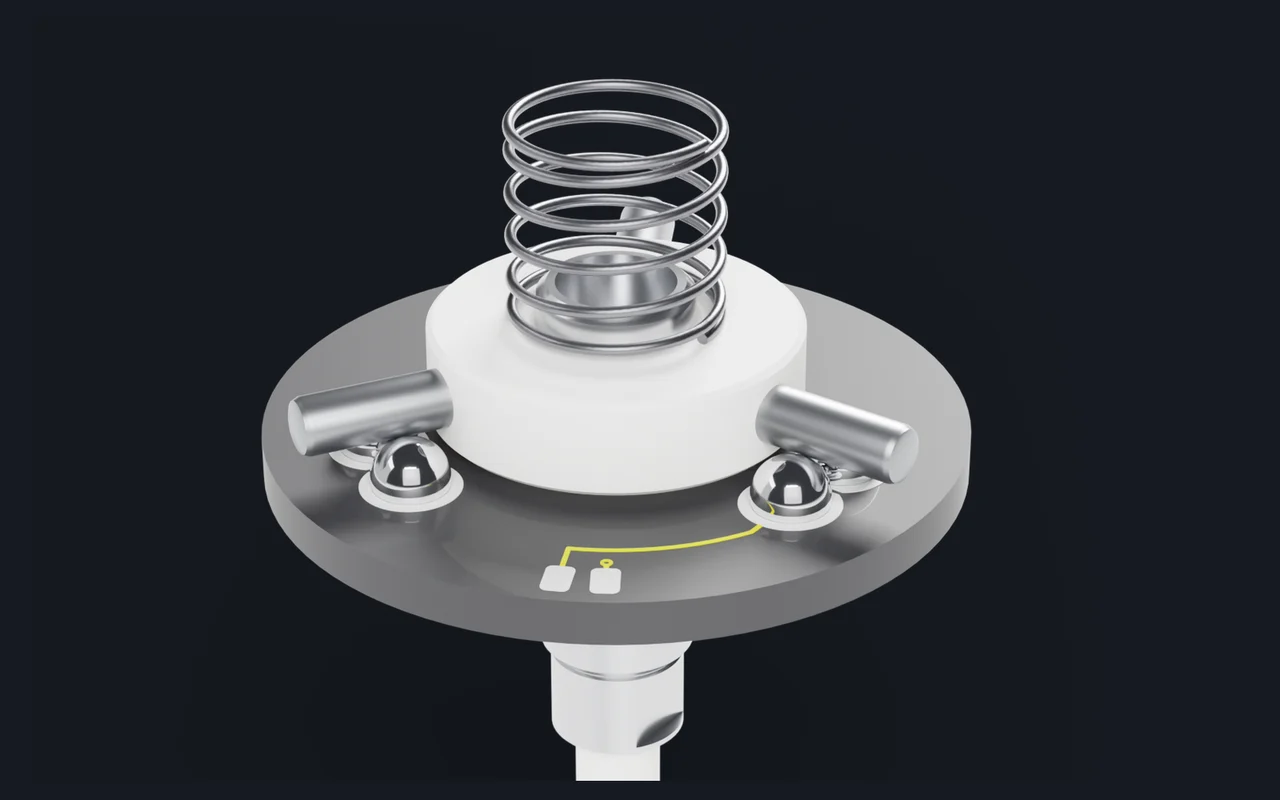
3pins on 6 balls

The stylus returns to the same place after every touch.

Ø42mm

Aluminium body in an ER32 chuck.

0.17ms

Infrared answer in the twin. Radio: 0.53 ms.

2signals

Infrared and 2.4 GHz radio. Either stops the robot, and so does losing both.
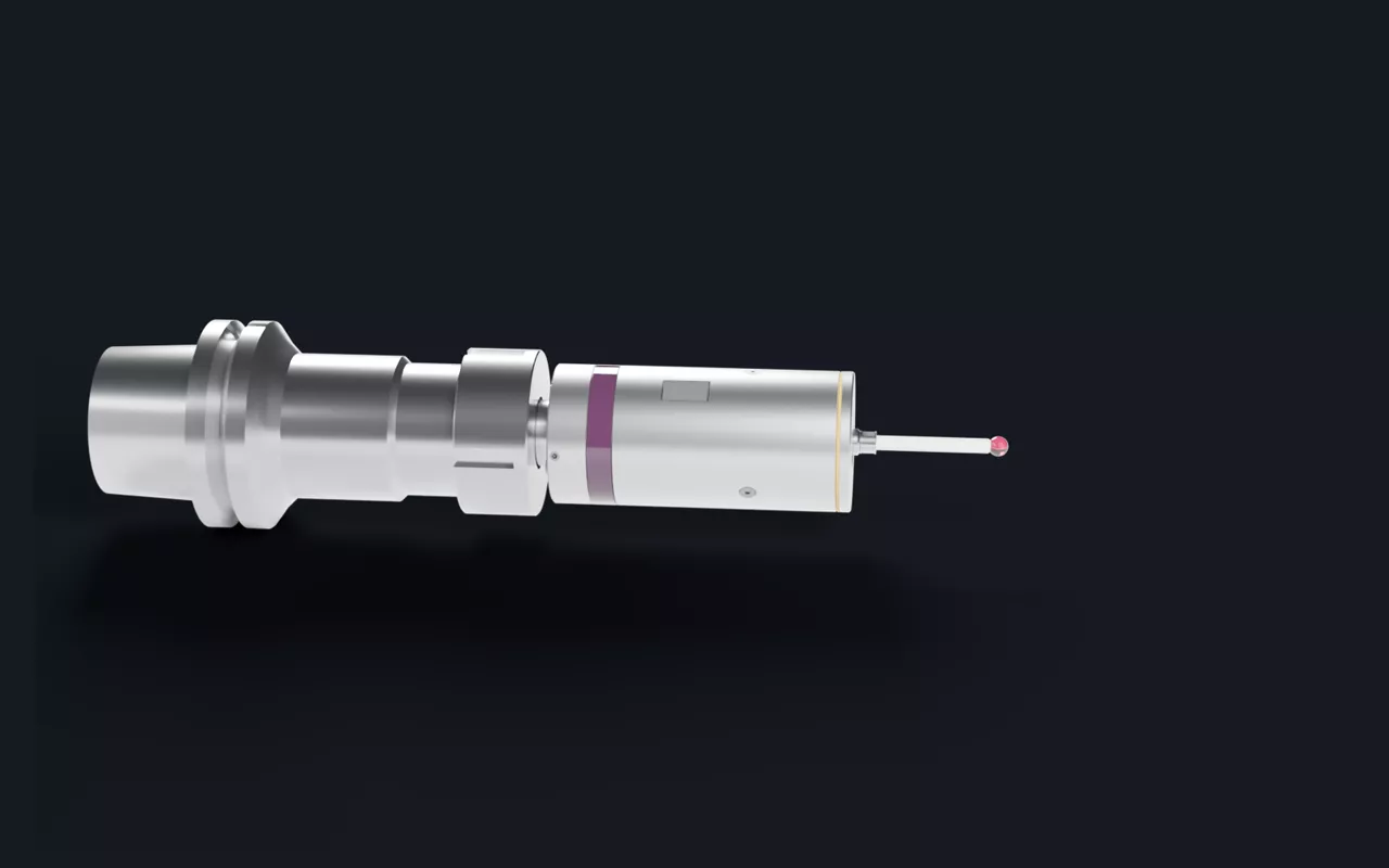
The probe in an ER32 chuck (render)
In the ER32 chuck · render
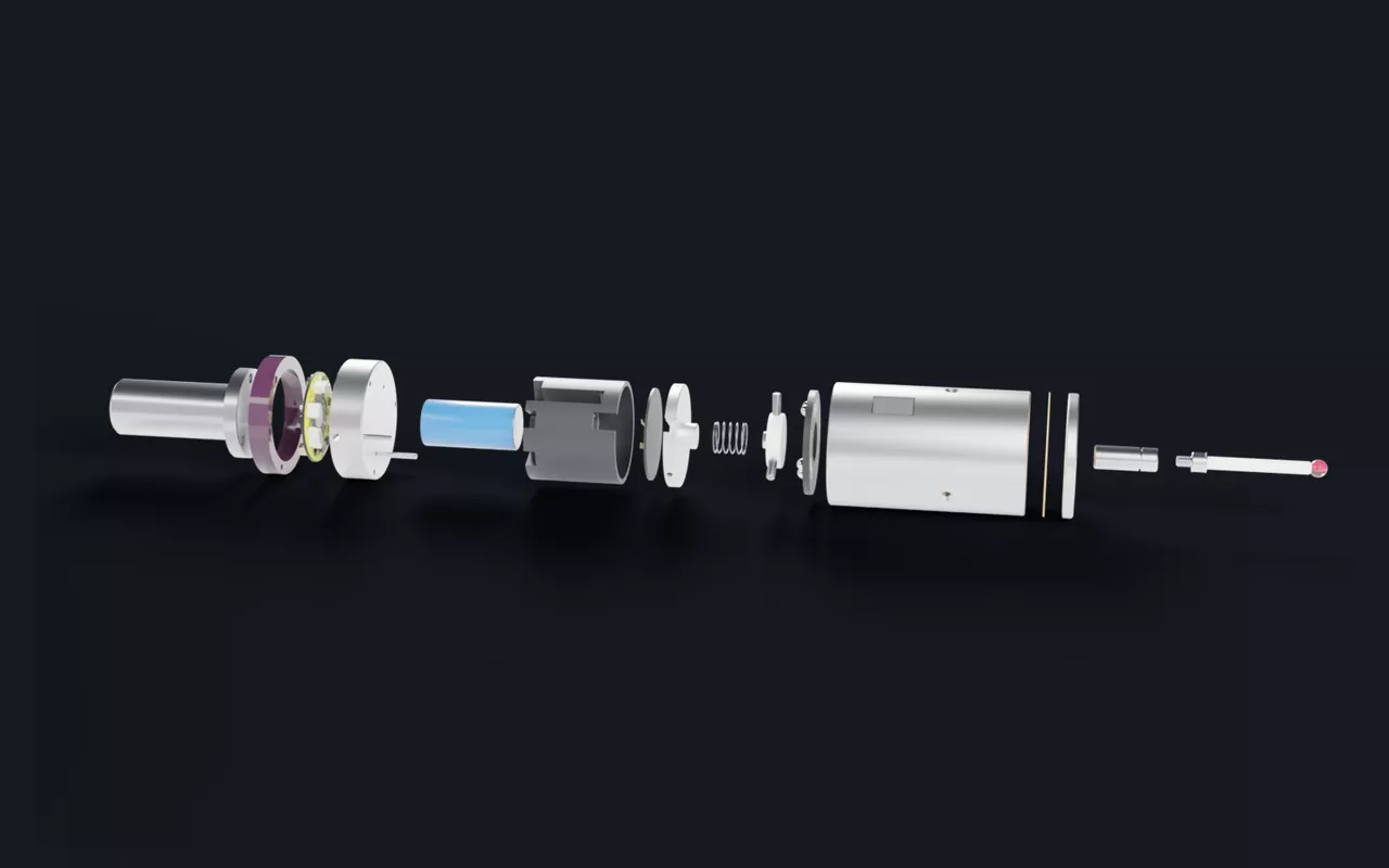
All parts of the probe (render)
Every part · render
Three pins on six balls (render)
The seat · render
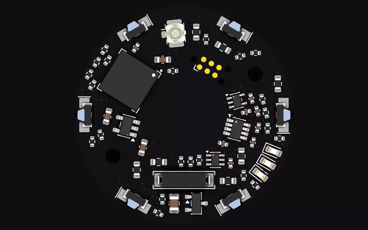
Main circuit board (render)
Main board · render
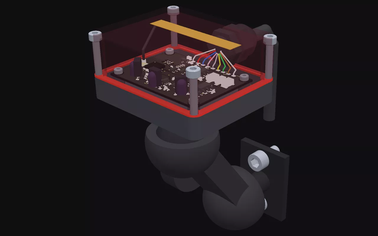
The receiver (render)
Receiver · render

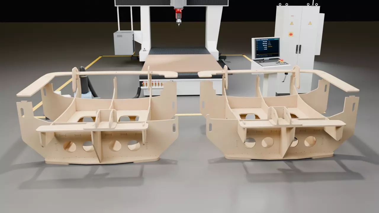
5-axis CNC: sheets to fixtures

Nested, programmed and checked per sheet. Render.

Fixture job on the KIMLA BFN 2141 · render
38

boards, slotted into two fixtures, from 7 sheets of birch plywood.

Gelcoat spraying

In development. Paths from the mould, coat thickness simulated on the GPU.
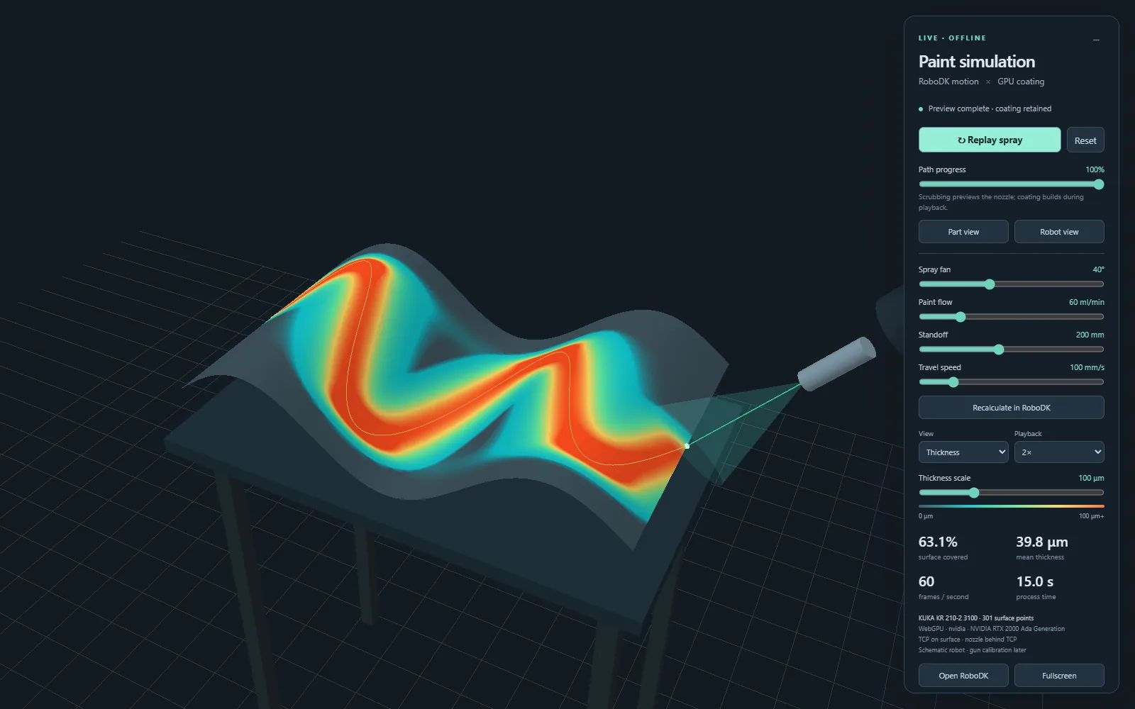
Simulated coat thickness
Coat thickness · simulated
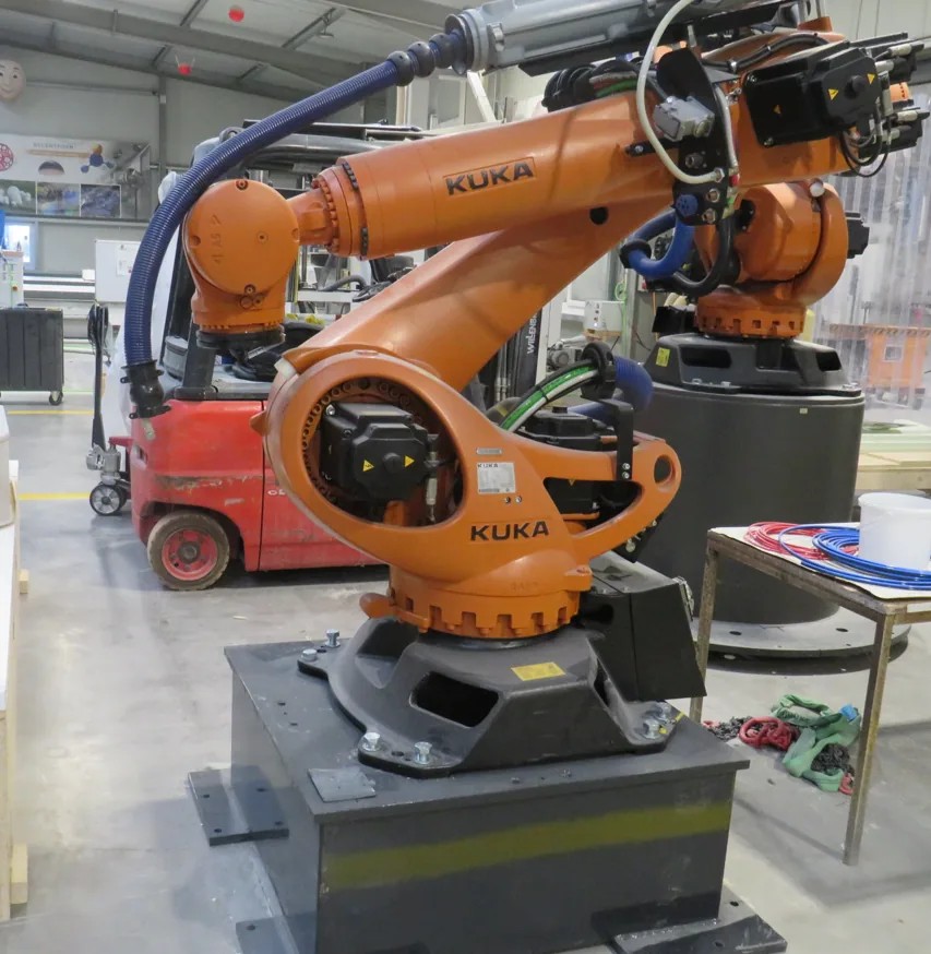
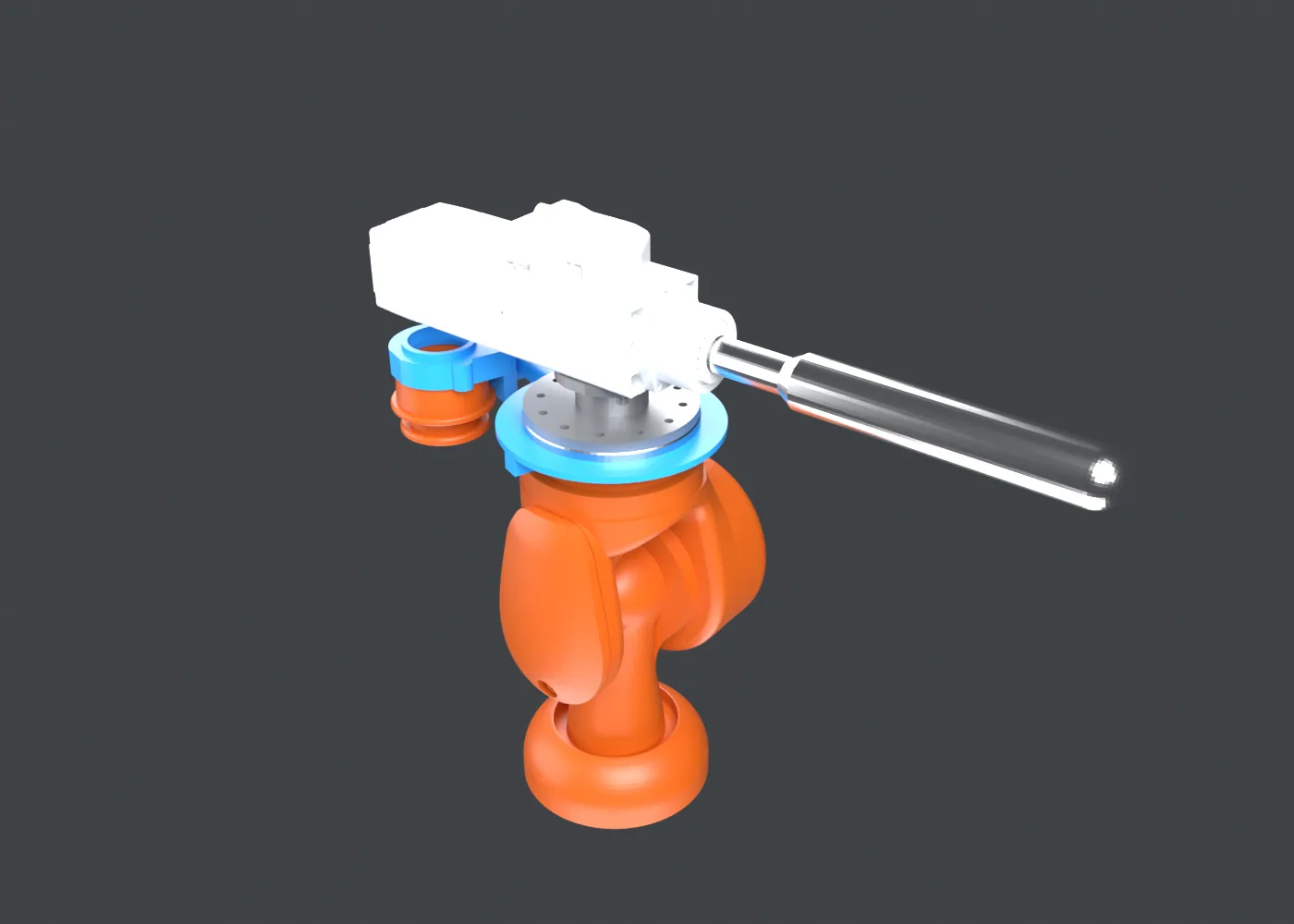
The spray cell's KUKA
KUKA KR 210 R3100 at ACCENTFORM

Our software

All written by us.

SeatStudio
In production

SeatStudio

CAM program in, checked KUKA program out.
Robot check
In production

Robot check

Reach, joints and collisions for every move.
Sheet nesting
In use

Sheet nesting

Boards on sheets, one program per sheet.
Tool measuring
In use

Tool measuring

The tool point from a camera.

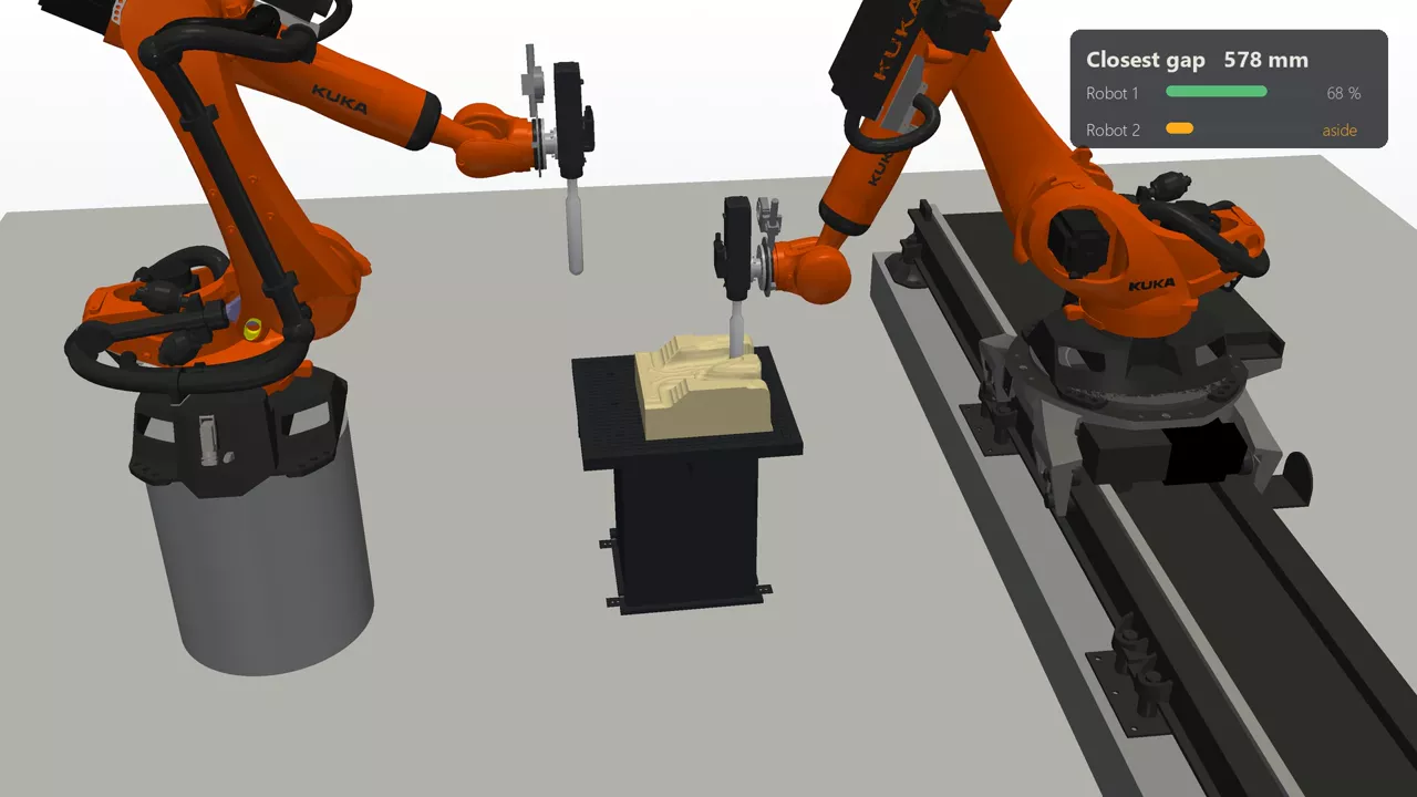
Two robots, one part
In development

Two robots, one part

One program split between two arms, kept 100 mm apart.

Spray paths
In development

Spray paths

From the mould's CAD, coat simulated first.
CAD, CAM and slicer in the browser
In development

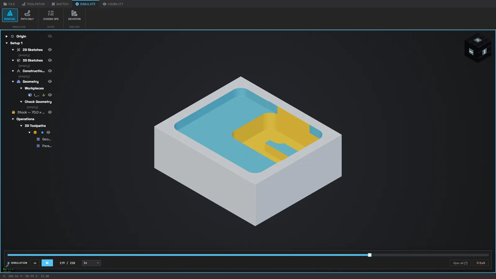
CAD, CAM and slicer

Model to machine in one browser app.

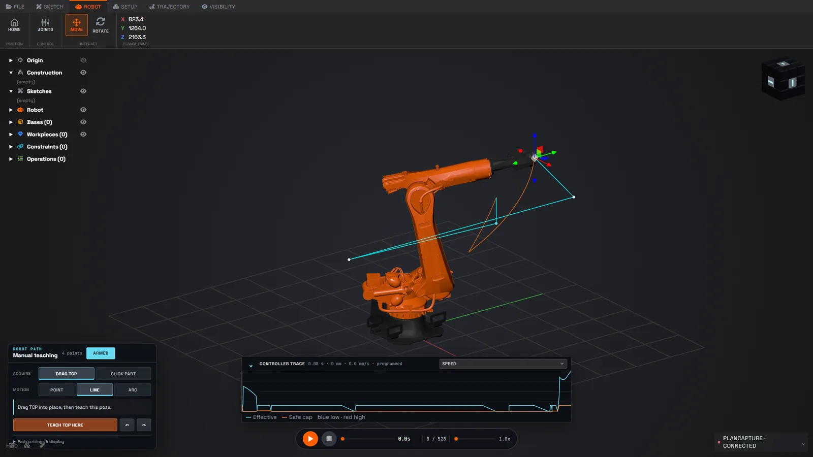
Robot paths and FEA in the browser
In development

Robot and FEA

Controller trace, and GPU finite elements checked against CalculiX.

Implicit CAM

In development. Toolpaths straight from the signed distance field, holder included.

Film · 41 s

Cut, print, spray, measure, build.